4 min read
Machine vision for quality control: requirements for effective implementation
Lighting, representative defect images and measured error rates play a central role in visual inspection performance.
On many production lines a person still looks at each part and decides whether it is good. Machine vision does that job with a camera and software: it takes a picture of every part, decides, and tells the line what to do with it. The idea is simple. Getting it to work reliably on a real line is mostly about things other than the algorithm, and this is a plain guide to what they are.
What it is used for
Visual inspection covers several different jobs, and it helps to know which one you have:
- Presence and completeness: is the cap on, the label there, every component on the board?
- Measurement: a length, a diameter, a gap, the position of a hole.
- Surface defects: scratches, dents, cracks, stains, missing paint.
- Reading: barcodes and 2D codes, printed dates and lot numbers.
- Guidance: finding where a part is and how it lies, so a robot can pick it up (we wrote about How a robot arm tracks a moving target).
Measurement and presence checks are usually the most straightforward. Surface defects on natural or varied materials are usually the hardest.
The picture comes first
No software can find a defect that the image does not show. The camera, the lens and above all the lighting decide what the image shows, and lighting is where many projects are won or lost. A few standard techniques do most of the work:
- Backlighting: the part between the camera and a light, so its outline is sharp. Good for dimensions and holes.
- Diffuse light, from a dome or a large panel, for shiny or curved surfaces that would otherwise reflect bright spots.
- Low-angle light from the side, so that scratches, dents and embossing throw small shadows and stand out.
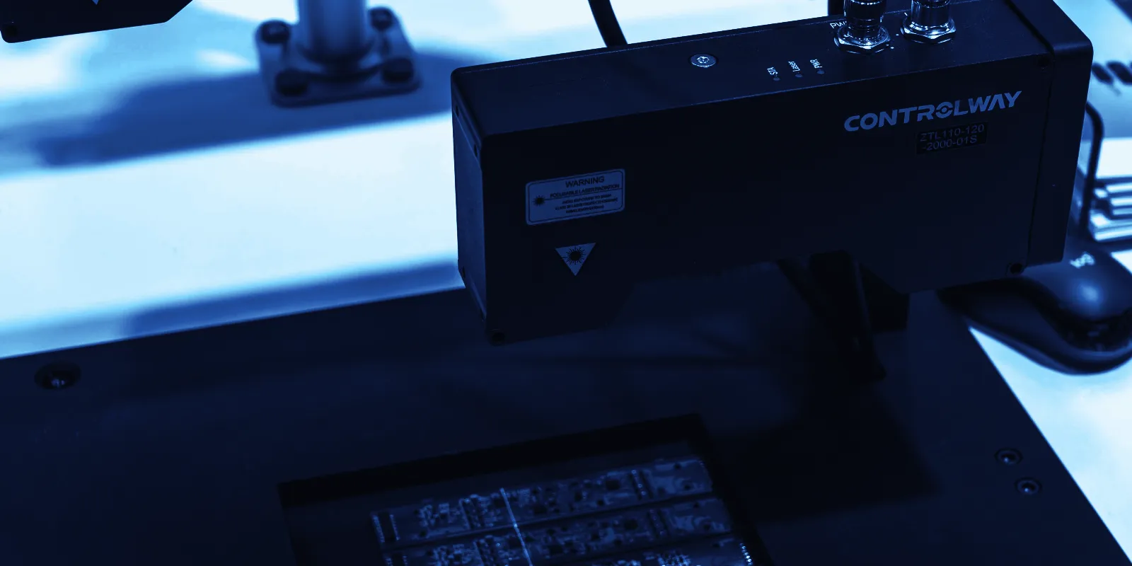
- A laser line or other structured light, viewed at an angle, to measure height and shape in 3D.
The camera has to be matched to the motion too. A part moving past the camera blurs unless the exposure is short or the light is strobed, and the picture must be taken at the right moment, usually triggered by a sensor or the conveyor's encoder. For material that runs continuously, such as sheet, film or textile, a line-scan camera builds the image one line at a time.
Before writing any software, it is worth testing lighting on real parts, good and defective, until the defects are clearly visible to a person looking at the screen.
Rules or learning
There are two broad ways to decide from the image.
Rule-based vision uses classic image processing: thresholds, edges, blobs, matching against a reference pattern, measured distances. It is precise, fast and easy to explain, and it remains the right tool for measurement and for defects that are clearly defined.
Deep learning trains a neural network on labelled examples to classify an image, detect defects or outline them pixel by pixel. It copes with variation that rules handle badly: wood grain, textiles, welds, food, surfaces where "normal" looks different every time. It needs examples, and its decisions are harder to explain.
When defects are rare, there is a third option: anomaly detection, trained mainly on images of good parts, which flags anything that looks unusual. It finds problems nobody listed in advance, at the cost of also flagging harmless variation until it is tuned.
In practice many systems combine them: rules to locate the part and measure it, a learned model to judge the surface.
The data is the project
For a learned model, the images matter more than the choice of network:
- Collect from the line itself, with the final camera and lighting. Images taken elsewhere look different.
- Defects are rare, so collecting enough of each kind takes time. Keep every rejected part's image.
- Agree on the labels with the people who own quality. Two inspectors often disagree on borderline parts, and the model learns whatever the labels say.
- Keep a test set that is never used for training, to measure the system honestly.
Production also changes: a new supplier, a new batch of material, a worn tool, a dirty lens. Plan to keep collecting images after launch and to check whether accuracy is drifting.
Measuring what matters
A visual inspection system makes two kinds of mistake:
- an escape: a defective part judged good and sent on;
- a false reject: a good part thrown out or sent for a second check.
Every system trades one against the other through its decision threshold. Which one costs more depends on the product: an escaped defect in a safety part is far worse than a few good parts re-checked by hand. Decide that first, then measure both rates on real production data, not on a handful of demonstration images. Where people do the inspection today, measuring them on the same set of parts gives a fair baseline.
Running on the line
A decision is only useful if it arrives before the part reaches the place where it can be removed. That usually means running the model on a computer next to the camera rather than in a distant data centre (more on that in Edge AI: considerations when moving models beyond the data centre), and connecting the result to the line's controller and its reject mechanism. Logging the images of rejected and borderline parts, with the decision and the time, makes problems traceable and gives the next round of training its data.
Where to start
- Pick the one defect or check that costs the most today.
- Get the image right: camera, lens and lighting tested on real good and bad parts.
- Run a pilot that measures both escapes and false rejects on real production.
- Only then widen it to more defects or more lines.
Contact us to discuss visual inspection for your production line.